
Bidirectional ARM Assembly Syntax Specifications
![]() One of the tantalising pieces of information contained in ARM’s machine
readable specifications is a specification of the assembly syntax.
A few years ago (on an earlier) version of the specification, Wojciech Meyer
and I decided to try to transform this specification into assemblers and
disassemblers.
At the time, this was not very useful to ARM because we already had assemblers
and disassemblers so, although technically successful, the project died and
the code has been slowly bitrotting ever since.
In a few days time, I will be giving a talk at the 34th Chaos Communication
Congress
[video]
[pdf]
in
Leipzig about practical things you can do with ARM’s specification and
I thought it would be a good idea to suggest that someone creates a similar
tool.
But maybe it would be a good idea if I showed you what Wojciech and I did to
get you started?
One of the tantalising pieces of information contained in ARM’s machine
readable specifications is a specification of the assembly syntax.
A few years ago (on an earlier) version of the specification, Wojciech Meyer
and I decided to try to transform this specification into assemblers and
disassemblers.
At the time, this was not very useful to ARM because we already had assemblers
and disassemblers so, although technically successful, the project died and
the code has been slowly bitrotting ever since.
In a few days time, I will be giving a talk at the 34th Chaos Communication
Congress
[video]
[pdf]
in
Leipzig about practical things you can do with ARM’s specification and
I thought it would be a good idea to suggest that someone creates a similar
tool.
But maybe it would be a good idea if I showed you what Wojciech and I did to
get you started?
The ARM assembly specification
Let’s start by digging into the HTML rendering of the ARM spec with the ADD instruction. The assembly syntax is in four parts. The first two parts show you the opcode diagram and the overall assembly syntax and is almost directly usable as a specification.
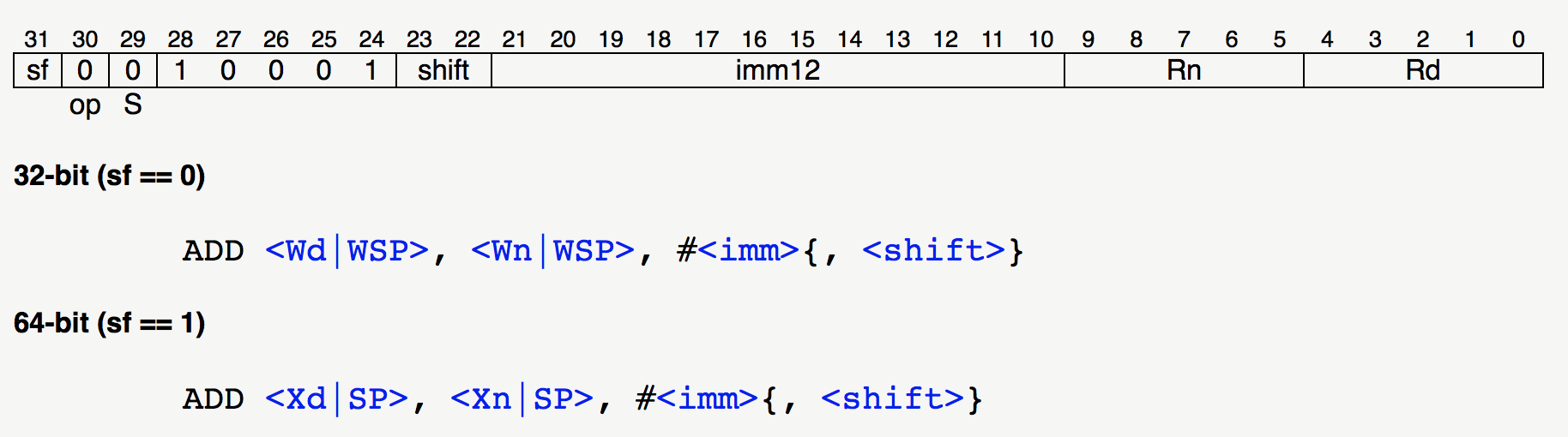
The third part describes what symbols like “<Wd|WSP>” mean and will take a bit of massaging into usable form.
And the final part describes aliases such as using “ADD <Wd>, <SP>, #0” as an alias for “MOV <Wd>, SP”. This consists of a link to a page describing the alias and a condition written in ASL for when the alias is legal/preferred.

And, all this information is present in the XML file so it is very easy to extract.
The only thing that is not quite usable in the above is the assembler symbols. So let’s think about what we could use instead.
A better spec of the assembler symbols
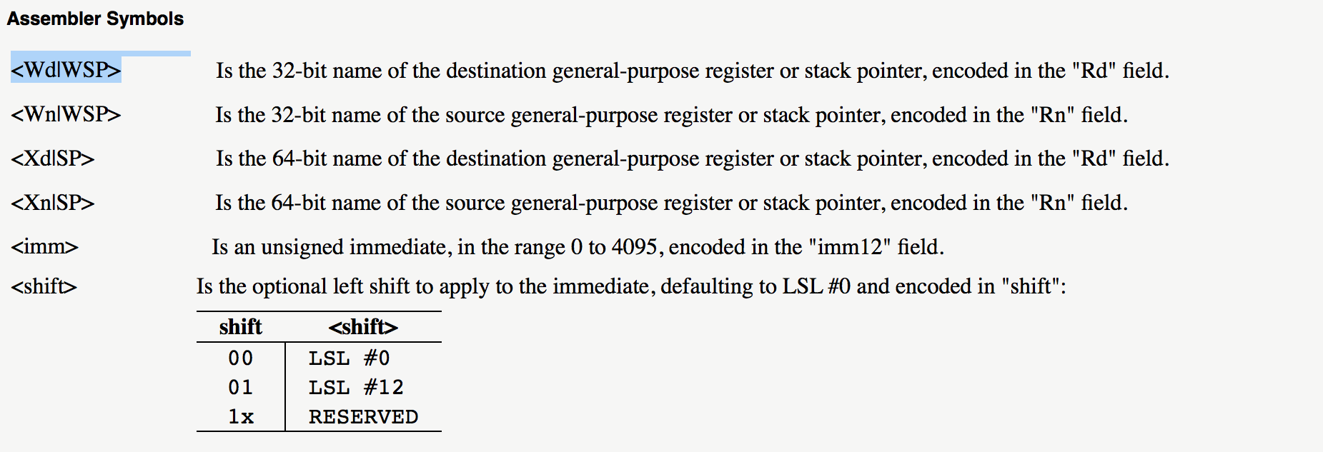
The assembler specification is full of sentences like “Is the 64-bit name of the destination general-purpose register or stack pointer, encoded in the “Rd” field.”
All that means is that, given the field “Rd” that the opcode defines as a 5-bit field in bits 4:0 of the opcode, we need to generate a string that will either be “X0”, “X1”, … “X30” or “SP”. This pattern is going to come up a lot so let’s extend ARM’s Architecture Specification Language (ASL) with a new function “RegXSP”
string RegXSP(integer x)
    if x == 31 then
        return "XSP";
    else
        StringConcat("X", DecimalString(x));
With this function, we can now define what the symbol “<Xd|SP>” means in ASL
<Xd|SP> = RegXSP(UInt(Rd));
(Wherever possible, I prefer to keep the formal specification as close to the original specification as possible. So I am choosing to allow identifiers to have normal looking syntax like “Rd” and some funky syntax like “<Xd|SP>” and “<imm>”.)
In the same way, I can define most of the rest of the assembler symbols
<Xd|SP> = RegXSP(UInt(Rd));
<Xn|SP> = RegXSP(UInt(Rn));
<imm>   = DecimalString(UInt(imm12));
But the “<shift>” symbol is a bit more complicated because it is optional and it is defined using a table.
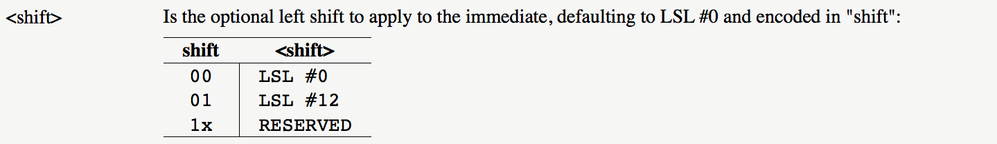
One of the things I noticed comparing the English prose parts of ARM specifications with their formal counterparts is that tables in text often correspond to case expressions or case statements in ASL. So I decided to translate the table into a case expression.
case shift {
    '00' <-> "LSL #0";
    '01' <-> "LSL #12";
    '1x' <-> RESERVED();
}
(Note that the discriminant in this expression is the opcode field “shift” which we should not confuse with “<shift>” which is the assembler symbol we are trying to define.)
To deal with the fact that the field is optional, I decided to define another function “Optional” that will throw an exception if its input matches some pattern and, otherwise, will return its input
string Optional(string pattern, string x)
    if x == pattern then
        throw OPTIONAL;
    else
        return x;
(This would probably be better handled by having the function return “Option[string]” but ASL does not currently support this kind of type constructor.)
With this in place, we can finish the definition of “<shift>”
<shift> = Optional("LSL #0",
          case shift {
           '00' <-> "LSL #0";
           '01' <-> "LSL #12";
           '1x' <-> RESERVED();
          });
And our complete specification of the assembly syntax is as follows.
[sf:'1'; op:'0'; S:'0'; '10001'; shift:'xx'; imm12:'xxxxxxxxxxxx'; Rn:'xxxxx'; Rd:'xxxxx']
<->
"ADD" " " <Xd|SP> "," " " <Xn|SP> "," " " [ "#" ] <imm> " " [ "," " " <shift> ]
    where
        <Xd|SP> = RegXSP(UInt(Rd));
        <Xn|SP> = RegXSP(UInt(Rn));
        <imm>   = DecimalString(UInt(imm12));
        <shift> = Optional("LSL #0",
                  case shift {
                   '00' <-> "LSL #0";
                   '01' <-> "LSL #12";
                   '1x' <-> RESERVED();
                  });
Using the specification as a disassembler
We can execute this specification as follows.
-
Check whether the opcode matches each field of the pattern at the top. A bit position in the field pattern is either ‘1’, ‘0’ or ‘x’ which means either 1 or 0.
-
Extract the value of each named field of the opcode. So, from ‘0x9104_0001’ we extract
sf = '1' op = '0' S = '0' shift = '00' imm12 = '0001 0000 0000' Rn = '00000' Rd = '00001' -
Evaluate each term of the overall assembly syntax. Literal strings evaluate as themselves, identifiers such as “<Xd|SP>” trigger evaluation of the corresponding definition and “[ … ]” indicates an optional field. If evaluating an optional field throws an OPTIONAL exception, the result is an empty string. All the resulting strings are concatenated to get the complete disassembly.
In this case, the assembler symbols evaluate to
 <Xd|SP> = "X1"
 <Xn|SP> = "X0"
 <imm>   = "256"
 <shift> = throw OPTIONAL
So the overall disassembly is
ADD X1, X0, #256
Using the specification as an assembler
More interestingly, we can execute the specification as an assembler by evaluating each expression in reverse. The way this works is that we interpret the overall assembly syntax as a grammar rule and try to match tokens in the syntax against the input.
For example, we can try to match the string
"ADD X1, X0, 256".
against this rule
"ADD" " " <Xd|SP> "," " " <Xn|SP> "," " " [ "#" ] <imm> " " [ "," " " <shift> ]
-
Match the first terminal “ADD” against the start of the string leaving “ X1, X0, 256”.
-
Match the second terminal “ “ against one or more spaces leaving “X1, X0, 256”.
-
Match the non-terminal “<Xd|SP>” by trying to match its definition “RegXSP(UInt(Rd))”.
-
Match “RegXSP(e)” by looking for a maximal string matching the regexp “X[0-9]*|SP”. If it matches, match the digit string or the string “31” against “e”. This gives the string “1” to be matched against “UInt(d)” and leaves the string “, X0, 256”
(I treat “RegXSP”, “UInt”, etc. as builtin functions that the assembler just “knows”. I have about 20 builtins like this so this is not too much work but you could probably get away with less.)
-
Match “1” against “UInt(Rd)” and bind the variable “Rd” to the bitvector “00001”.
-
Similarly, we match “<Xn|SP>” and bind “Rn” to the bitvector “00000” leaving “, 256”.
-
Match the nonterminals “,” and “ “ against “, “ leaving “256” to be matched.
-
The string “256” does not match “#” so skip the optional sequence in square brackets.
-
Match the non-terminal “<imm>” against “256” and bind “imm12” against ‘0001 0000 0000’ leaving an empty string to be matched.
-
The empty string does not match “,” so skip the optional sequence in square brackets but, since it contains a non-terminal, try to match it against “throw OPTIONAL”. This requires that the two arguments of “Optional()” match so we have to match the case expression “case shift { … }” against the string “LSL #0”.
-
Match the string “LSL #0” against the right hand side of each alternative in the case expression. It matches the right hand side of this alternative
'00' <-> "LSL #0"so bind the discriminant “shift” to the value ‘00’.
The result of all this is that the parse succeeded and we have the following bindings
Rd    = '00001'
Rn    = '00000'
imm12 = '0001 0000 0000'
shift = '00'
so we can assemble the complete bitvector:
[sf:'1'; op:'0'; S:'0'; '10001'; shift:'00'; imm12:'0001 0000 0000'; Rn:'00000'; Rd:'000001']
giving the opcode 0x9104_0001.
Transforming the assembler symbols spec into ASL
Now that we know what we want the definition to look like, we need some way to transform ARM’s specification into the ASL extension sketched above. The tables are clearly represented in the XML representation but what are we to do with all that English prose? The approach that Wojciech and I used is a bit brute force, a but ugly but it got the job done. We made a list of all the unique strings we needed to match across all the different instructions and wrote a series of regexps to match them all. For example here are some of the replacements used for references to registers
// Handling of general register fields
s = s.replace(" 32-bit register or SP",     " REG_WSP")
s = s.replace(" 32-bit general register",   " REG_WZR")
s = s.replace(" 64-bit general register",   " REG_XZR")
s = s.replace(" half-precision register",   " REG_H")
s = s.replace(" single-precision register", " REG_S")
s = s.replace(" double-precision register", " REG_D")
s = s.replace(" 8 bit FP/SIMD register",    " REG_B")
These help to normalise the different ways of referring to registers so that later patterns like these can finish the job off.
s = s.replaceAll("Is the (.*)REG_([^ ]*) (.*)encoded in \"(.*)\" plus (.*) modulo 32", "Reg(\"$2\",(UInt($4)+$5) MOD 32)")
s = s.replaceAll("Is the (.*)REG_([^ ]*) (.*)encoded in \"(.*)\".  Defaults to (.*) if absent", "optional(\"$5\",Reg$5(\"$2\",UInt($4)))")
s = s.replaceAll("Is the optional (.*)REG_(X[^ ]*) defaulting to '11111' encoded in \"(.*)\"", "optional(\"XZR\",RegXZR(\"$2\",UInt($3)))")
This is the part of our work that has bitrotted the most so I won’t show any more of this — but hopefully you get the idea.
Conclusion
This part of the project to formalise the ARM architecture specification was both a technical success and a tech transfer failure.
On the one hand, it worked: we tested the disassembler against hand-written disassemblers on all 2^32 encodings; we tested that assembling the disassembly of any opcode results in the same opcode on all 2^32 encodings.
But, there was no demand within the company for this work because ARM already hand-written assemblers and disassemblers and because the GNU assembler contribution rules would have required contribution of the source files that we use to generate the XML and all the scripts that generate the XML and lots and lots of other parts of the sausage factory. So, with no potential consumer of my improved specification, I was not able to persuade the team maintaining the assembly specification to change to my ASL-based syntax instead of English prose.
That is the way it is in industrial research sometimes: timing is a very important part of successful research projects.
People have written to tell me about similar projects for ARM disassembly:
- Agustin Gianni wrote retools: a reverse engineering toolkit for normies based on scraping the assembly syntax out of PDF files.
- Nick Spinale is writing hs-arm based on the XML spec.
Related posts and papers
- Paper: End-to-End Verification of ARM Processors with ISA-Formal, CAV 2016.
- Verifying against the official ARM specification
- Finding Bugs versus Proving Absence of Bugs
- Limitations of ISA-Formal
- Paper: Trustworthy Specifications of ARM v8-A and v8-M System Level Architecture, FMCAD 2016.
- ARM’s ASL Specification Language
- ARM Releases Machine Readable Architecture Specification
- Dissecting the ARM Machine Readable Architecture files
- Code: MRA Tools
- ASL Lexical Syntax
- Arm v8.3 Machine Readable Specifications
- Paper: Who guards the guards? Formal Validation of the Arm v8-M Architecture Specification), OOPSLA 2017.
- Are Natural Language Specifications Useful?
- Formal validation of the Arm v8-M specification
- This post: Bidirectional ARM Assembly Syntax Specifications
- Talk: [How can you trust formally verified software (pdf)], Chaos Communication Congress, 2017.
The opinions expressed are my own views and not my employer's.